I. Overview
There are 2 flame cutting machines in the 5# continuous casting of steelworks, and 1 flame cutting machine in 3# continuous casting is not equipped with dust removal system. During the cutting process, a large amount of smoke will be generated, polluting the workshop, and a treatment plan will be formulated for this pollution situation.
Current workshop situation:
Design Basis
2.1, design standards, specifications
Environmental Protection Law of the People's Republic
"Environmental Air Quality Standards" GB3095-1996
"Water pollutant discharge standards for iron and steel enterprises" GB13456~92
"Emission Standards for Pollutants in Industrial Furnaces" GB9078-96
"Integrated Emission Standards for Air Pollutants" GB 16297-1996
《Pulse-blowing bag type dust collector》 JB/T 8532-1997
Power Machine Basic Design Specification GB 50040-96
"Design Specification for Low Voltage Distribution" GB 50054-95
"Code for Design of Gas Transmission Pipeline Engineering" GB 50251-94
"Code for Construction and Acceptance of Industrial Metal Pipeline Engineering" GB 50235-97
General Rules for the Use of Industrial Products GB 9969.1-1998
"Code for construction and acceptance of field equipment and industrial pipeline welding engineering" GB 50236-98
2.2, manufacturing standards, specifications
Welding Quality Assurance GB/T12469-90
Casting Weight Tolerance GB/T11351-89
Guidelines for Sampling Inspection GB/T13393-92
"Color and varnish Determination of film thickness" GB/T13452.2-92
"Ventilator field test" GB/T10178-88
General technical conditions for mechanical and electrical product packaging GB/T13384-92
"Fixed Industrial Steel Platform" GB/4053.4-93
"Safety Technical Conditions for Fixed Steel Straight Ladders and Inclined Ladders" GB/4053.1~2-93
"Safety Technical Conditions for Fixed Industrial Protective Railings" GB/4053.3-93
"Code for Construction and Acceptance of Steel Structure Engineering" GB50205-2001
General Rules for Industrial Product Assurance Documents GB/T14436-93
2.3, design technical indicators
1), the collection rate of the dust removal system is >95%
2) Dust removal efficiency of dust removal system >99.9%
3), dust removal system dust removal concentration <15mg/m3
Third, the design description
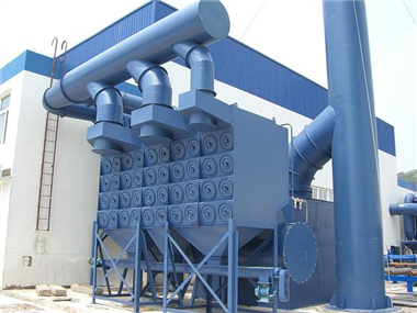
The flame cutting machine is a device that can be moved on the landing track. Therefore, the collection of soot generated during the production of the device also needs to be collected according to its movement. For this case, the flame cutting machine is considered. The side of the landing track is arranged with the air channel slot and the air channel slot car, so that the air channel slot car and the flame cutting machine run synchronously, and the smoke is collected in the dust collecting hood and then the dust is transmitted to the air channel slot through the air channel slot car. The dust is then introduced into the dust removal station through the connecting pipe for treatment and then emptied.
Fourth, the scope of design:
The process, equipment, building structure, electrical control and instrumentation of the dust removal system project are considered by this plan.
The specific design content is:
1 Dust removal system process design
2 Structural design of the flue gas capture hood
3 Dust removal system pipe network design
4 Dust removal equipment design and selection
5 fan and motor selection design
6 dust collector unloading ash system design
7 Supporting electrical and control system design
Five, design principles
1) Under the premise of ensuring the relevant emission standards, optimize the dust removal equipment to reduce investment as an aspect of design consideration.
2) Optimize the design so that the project is put into place once and the dust removal effect meets environmental protection requirements.
3) Reduce power consumption as much as possible and reduce operating costs.
4) Ensure equipment safety, strive for the advanced nature of comprehensive benefits, and improve dust collection rate
5), minimize system resistance and improve dust removal effect
6), with the host operating rate of 100%, easy to repair.
Sixth, the selection of dust removal process
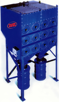
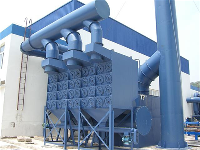
Our company chooses PKF purifier, the structure and working principle of the equipment: pulse filter cartridge dust collector is equipped with air inlet, filter cartridge, air outlet, air bag, pulse controller, injection valve, blow pipe, etc. The polyester fiber is folded and rolled, and its lower end is closed, and the center of the upper end is opposite to the lower end of the blowing pipe. After the dust-containing gas enters the dust collector from the air inlet, the airflow speed is slowed down, and the coarse particles are separated from the airflow and settled into the dust collecting chamber. The fine dust is blocked on the outer surface of the filter cartridge when the airflow passes through the filter cartridge, and the clean gas is discharged from the air outlet; When the ash layer on the surface of the filter cartridge is thick, the pulse controller gives an instruction to open the injection valve, and the compressed air in the air bag is ejected at a high speed through the blowing pipe, and simultaneously induces several times the ambient air of the injected gas to enter the filter cartridge, and from the inside to the outside. Quickly shoot out, the dust on the outer surface of the filter cartridge is blown into the dust collection chamber, and finally discharged by the ash hopper. The dust collector is cleaned by pulse injection, which not only completely cleans the dust, but also does not damage the filter cartridge, so that the service life of the filter cartridge can be guaranteed. The cleaning process is automatically controlled by the pulse controller and can be controlled by pressure difference or time.
Features:
1. High dust removal efficiency, good filtering effect, small size and stable operation.
2. The filter cartridge is installed by skeleton, and the sealing performance is good, firm and reliable.
3. The filter cartridge has a long service life and is convenient for installation and maintenance.
4. The cabinet is airtight and has good sealing performance. The door is cleaned with excellent sealing material and the air leakage rate is very low.
5. The inlet and outlet air ducts are arranged compactly and the airflow resistance is small.
6. The filter replacement time is short, no dust is flying, there is no safety hazard to the workers. It is not necessary to open the dust collector, disassemble the blow pipe, pull out the bag cage and then pump the filter bag. The worker is gray in the dust collector and there is danger of working at height. Sex.
Working condition:
Sheet metal processing: robot welding, plasma cutting, laser cutting, laser welding, steel shot blasting, steel plate polishing, etc.
Function: oil mist air, steam mist air, welding flue gas, dust air purification, paint smell, polishing dust, sand blasting purification, and the purified gas is directly discharged into the workshop.
Untreated hazards: oil mist, dust, harmful gas hazards and energy saving
[Human Effects]--0.3-3.5 micron particles will inhale into the human body and pose a health hazard. Oil mist is deposited in the work area, which may cause accidents such as work-related injuries.
[Work efficiency]--If the workplace fog temperature, reduce production efficiency.
[Working environment], wasting resources]--If the mist is discharged to the outside, it will damage the environment; if it is effectively recycled, it can save resources.
[Impact of fire alarm]--The oil mist is deposited on the wall, and there are potential fire hazards on the equipment.
[Impact of the device] - may be the cause of malfunctions inside the machine and electrical systems.
Seven, the main equipment of the dust removal system:
Since the two flame cutting machine stations of the 5# continuous casting are close to each other, a dust removal system can be shared for soot treatment (two flame cutting machines have only one flame cutting machine at the same time); one flame for 3# continuous casting The cutting machine is separately equipped with a dust removal system for dust removal.
7.1, dust collector design technical parameters:
Pau Dak PKF flue gas purifier selection table
model
PKF1-2-2
PKF1-3-3
PKF1-4-4
PKF2-2-4
PKF2-3-6
PKF2-4-8
PKF3-2-6
PKF3-3-9
PKF3-4-12
(PZF) total filtration area m2
40
60
80
80
120
160
120
180
240
(PGF) total filtration area m2
20
30
40
40
60
80
60
90
120
Filtration area m/min
0.5-1
(PZF) processing capacity m3/h
1920
2800
3840
3840
5760
7680
5760
8640
11520
(PGF) processing capacity m3/h
960
1400
1920
1920
2880
3840
2880
4320
5760
(PZF) motor power kw
3
5.5
7.5
7.5
11
15
11
15
18.5
(PGF) motor power kw
1.5
2.2
3
3
5.5
7.5
5.5
11
11
Filter cartridge size mm
Φ324*660
Filter cartridge installed capacity (a)
2
3
4
4
6
8
6
9
12
Number of pulse valves
2
3
4
4
6
8
6
9
12
Dust collection efficiency %
99.99
Working temperature °C
0~125
Filtering accuracy um
0.5~1000
Export dust concentration mg/m3
1~50
Dimensions
(length * width * height) mm
1480*
550*
2010
1480*
550*
2507
1480*
550*
3004
1480*
1000*
2010
1480*
1000*
2507
1480*
1000*
3004
1480*
1500*
2010
1480*
1500*
2507
1480*
1500*
3004
Remarks filter material
(PZF) nano wood pulp fiber, (PGF) long fiber polyester, (PWF) non-woven cotton and other materials, the above parameters are calculated according to the technology of (PZF) nano wood pulp fiber filter cartridge, using different filters Technical data will be subject to change. Consult PALDEK Technical Department in detail
Applicable working condition range
Welding fumes, laser cutting flue gas, dust recovery, air purification
1: Filter cartridge dust collector model: PKF3-4-12*120M2
(PGF) processing capacity 5760m3/h (6 units)
Designed to handle air volume: 30000 m3/h
Actual throughput: 34560m3/h
Total filtration area: 720m2
Filtration wind speed: 0.7m/min
Dust collection resistance: <1500Pa
Number of filter cartridges: 72
Filter cartridge specifications: 320 × 660mm,
Filter material: 250 g/m2 polyester non-woven film
Filter material material temperature: <120 °C
Dust concentration of imported gas: <5g/m3
Dust concentration of outlet gas: <15mg/ m3
The dust collector is subjected to negative pressure: <6000 Pa
Pulse pressure 0.3-0.6mpa
Compressed air consumption 0.2m3/min
Pulse valve: 72
Pulse valve specifications 1" pulse valve
2: Front flame arrester model: PKH30000 m 3/h
Designed to handle air volume: 30000 m3/h
Actual throughput: 35000m3/h
Dust collection efficiency: 85%
3: conveyor system
Screw feeder: PLX-1m 3/h 1 set
7.2, induced draft fan
The device is the power device of the system.
Model: G4—73—10D
Flow rate: 30000 m3 / h
Full pressure: 3700-4000Pa
Main motor power: about 55 KW 380V
7.3. Air duct slot and duct slot car assembly
The conveying device adopts a structure of a belt sealing air duct slot car and a belt sealing gas collecting main pipe, and realizes a seamless structure between the dust removing device and the moving production device through the structural form of the belt sealing car as the lifting device and the synchronous walking of the production device. The point-to-point communication method eliminates the complicated mechanism of the traditional touch port and simplifies the complicated operation of the operator. The schematic of the assembly is as follows:
Eight, dust collector introduction
8.1, the resistance control of the dust collector
The resistance of the dust collector is divided into two parts.
8.1.1. The design resistance of this equipment is <1500Pa.
Part of the resistance of the precipitator is the inherent resistance of the equipment (ie, the original resistance), which is caused by the individual smoke flow paths of the equipment.
Whether the dust collector enters and exits the air and the flow rate of the dusty airflow in each part of the air inlet duct is appropriate; whether the air inlet is at a distance from the bottom of the filter cartridge is sufficient for the flow of the dust-containing gas; the filter cartridge diameter and the filter cartridge spacing determine the filter The rationality of the flue gas lifting speed between the cylinders; the reasonable selection of the outlet pipe wind speed will affect the inherent resistance value of the precipitator.
The original resistance of the device is around 500Pa.
8.1.2. The second part is the operational resistance of the equipment.
The running resistance of the equipment is a cyclic value caused by the thickness of the ash layer formed on the surface of the filter cartridge during operation of the dust collector.
Generally, the upper limit of this value is set to 1200 Pa. When the device reaches this resistance value, the system starts cleaning, restores the resistance of the device to the original resistance, and enters the next cycle. The length of this cycle depends on the dust concentration of the flue gas and the specifications of the filter material.
8.2. Online detection (monitoring) equipment
In order to better protect the dust collector and realize on-line detection and monitoring of the dust collector, a series of online testing equipments are equipped for the dust removal system:
Differential pressure controller: control the cleaning system of the dust collector and analyze the cleaning effect and the life of the filter material through the cycle time of the working resistance of the equipment and the overall differential pressure of the dust collector after each cleaning;
Pressure gauge: online monitoring of the pressure of the compressed air system of the dust collector


 This site supports multi-terminal browsing
